Motor Shaft: The Precision Core – Powering Applications via Meticulous Design, Quality Materials & Reliable Rotation
I. Materials of Motor Shaft: “Bones and Muscles” Tailor-Made for Working Conditions
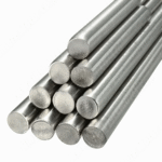
Carbon Steel Family for Motor Shafts: 1045 steel, with a carbon content of 0.45%, strikes a balance between a tensile strength of 400-600MPa and good toughness. The cold-rolled version has a surface precision of Ra1.6μm, suitable for low-load scenarios such as washing machines and air conditioners with household motor shafts; the hot-rolled version, though 15% lower in cost, has a surface roughness above Ra3.2μm, requiring more machining allowance, making it more suitable for equipment with loose precision requirements like industrial fans.

Alloy Steel for Motor Shafts: After quenching at 840°C and tempering at 540°C, 4140 alloy steel can reach a hardness of 30-40HRC, with its tensile strength surging to 800-1000MPa, easily bearing high torque above 1000Nm, thus becoming the “hardcore choice” for heavy machine tools and mining machinery motor shafts; 4340 low-alloy steel, with excellent hardenability, has an impact toughness 30% higher than carbon steel in low-speed, high-load equipment such as rolling mills.
Stainless Steel for Motor Shafts: 304 stainless steel, with salt spray resistance exceeding 500 hours, has outstanding corrosion resistance. Although its tensile strength is only 500-700MPa, it is sufficient for the humid environment of food processing equipment motor shafts; 316 stainless steel, due to its molybdenum content, has 40% higher acid and alkali resistance, becoming the exclusive “protective armor” for marine pumps and chemical stirrers’ motor shafts.
- New Composite Materials for Motor Shafts: Carbon Fiber Reinforced Polymer (CFRP) is 60% lighter than steel, with a vibration attenuation rate of 30%. In new energy vehicle drive motor shafts, it can reduce high-speed rotation inertia by 40%, indirectly increasing range by 5%-8%, and has become a pioneer in the lightweight revolution of motor shafts.
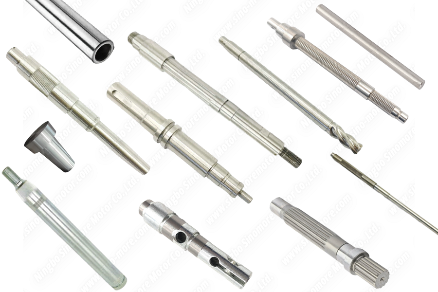
II. Types of Motor Shaft: Structure Defines Mission, Details Determine Success
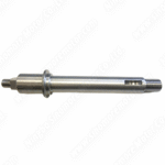
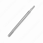
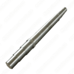
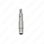
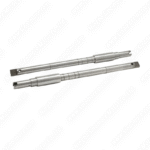
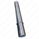
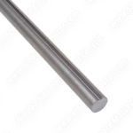
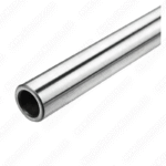
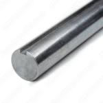
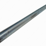
Solid Motor Shaft: A “versatile player” with a diameter of 10-100mm. Its design without redundant space makes its torsional section modulus (Wp) 25% higher than that of a hollow motor shaft of the same diameter. It is an irreplaceable “load-bearing pillar” in equipment such as injection molding machines and compressors that need to bear radial forces of 10-20kN.
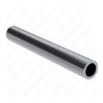
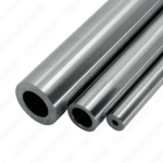
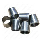
Hollow Motor Shaft: The inner hole diameter is mostly 1/3-1/2 of the outer diameter (e.g., 50mm outer diameter with 15-25mm inner hole). While reducing weight by 30%, the inner hole can be used to pass cooling water pipes or signal lines. In drone motor shafts (rotating speed >15000RPM), the airflow in the inner hole can reduce the working temperature by 8-12°C; on the rotating frame of medical CT machines, the inner hole paves a safe passage for cables.
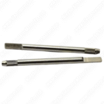
Keyed Motor Shaft: The precise fit of an 8mm wide key with a 3mm deep groove, through controlling the gap between the key and the hub to ≤0.02mm, increases torque transmission efficiency to over 98%. In industrial gearboxes, even with frequent forward and reverse rotations, the annual wear of the key can be controlled within 0.1mm, and the replacement cost is only 1/10 of the motor shaft body.
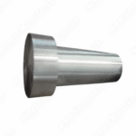
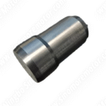
Tapered Motor Shaft: With a taper design of 1:10 or 1:20, it achieves “self-locking” through friction. In automobile wheel hubs, when the bolt preload reaches 2000N, the taper fit degree exceeds 95%, and the loosening risk during high-speed driving is 60% lower than that of flat key connection motor shafts.
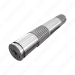
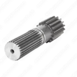
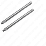
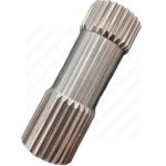
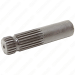
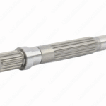
Splined Motor Shaft: With 6-32 longitudinal teeth (e.g., 40mm shaft with 10 teeth) of IT6 grade precision, the load error of each tooth during “multi-gear switching” of the gearbox is <5%, and its service life is 3 times longer than that of single-key connection motor shafts.
III. Manufacturing of Motor Shaft: The “Zero-Failure” Code in 0.01mm Precision
- Design Stage of Motor Shaft: Finite Element Analysis (FEA) is used to simulate the stress distribution of the motor shaft under 100,000 cycles of load, ensuring that the stress concentration factor at the journal transition fillet (R≥1.5mm) of the motor shaft is <1.2; through the critical speed formula (Nc=(C×d)/L²), it is guaranteed that the working speed of the motor shaft is 20% lower than the critical speed (e.g., the critical speed of a 10000RPM motor shaft must be >12000RPM).
- Processing Stage of Motor Shaft: CNC turning controls the diameter tolerance of the motor shaft to ±0.01mm, with concentricity ≤0.005mm; when EDM processes the keyway of the motor shaft, the surface roughness Ra≤0.8μm to avoid stress concentration risks; after heat treatment, magnetic particle testing (MT) is used to check for microcracks above 0.1mm on the motor shaft, eliminating “hidden wounds”.
- Surface Treatment of Motor Shaft: For motor shafts with high wear resistance requirements such as rolling mill shafts, carburizing treatment is adopted (carburized layer 0.8-1.2mm, surface hardness 58-62HRC); for marine equipment motor shafts, hard chrome plating is applied (thickness 20-50μm, salt spray test >1000 hours); the precision bearing mating surface of the motor shaft is superfinely ground to Ra0.4μm, reducing bearing temperature rise by 3-5°C.
IV. Maintenance of Motor Shaft: “Millimeter-Level” Guidelines for Extending Service Life
- Alignment Accuracy of Motor Shaft: Laser alignment instruments detect parallel deviation ≤0.05mm/m and angular deviation ≤0.02mm/m for the motor shaft; otherwise, for every 0.1mm increase in deviation, bearing life is shortened by 20%; new equipment requires secondary calibration after 3-6 months of operation to cope with the impact of foundation settlement on the motor shaft.
- Dynamic Balance of Motor Shaft: High-speed motor shafts (>3000RPM) need to reach G2.5 balance grade (residual unbalance ≤2.5g・mm/kg); for every 1g increase in vibration acceleration, bearing life is halved. It is recommended to recheck the motor shaft with a dynamic balancing machine every year.
- Lubrication and Protection of Motor Shaft: The grease at the bearing fit of the motor shaft should be replaced every 1000-5000 hours (take the lower value for high-speed motor shafts), with the filling amount being 1/2-2/3 of the bearing cavity; excessive filling will cause stirring heat, increasing temperature by more than 10°C; in humid environments, check the motor shaft’s coating quarterly, and promptly touch up if there is peeling larger than 0.5mm²; stainless steel motor shafts should avoid contact with carbon steel (to prevent galvanic corrosion, which can increase the rate by 3 times).
- Fatigue Detection of Motor Shaft: For high-load motor shafts that have been in operation for more than 10,000 hours, ultrasonic testing (UT) is used to check for internal cracks above 0.2mm. Special attention should be paid to stress concentration areas such as shaft shoulders and keyways of the motor shaft — the crack propagation speed here is 5-8 times that of the smooth surface.