Commutator: The Current Heart of Drive Motors – Structural Principles, Technical Challenges, and Application Analysis
In the motor operation system, the commutator, serving as the “intelligent hub” that maintains the motor’s efficient operation, has a core function: to ensure stable power output by continuously and accurately controlling the direction of the current. When the motor starts, the brush forms a dynamic conductive connection with the commutator’s surface. As the commutator rotates at high speed, its surface commutator segments (copper bars) sequentially make contact with the brush, converting external direct current (DC) into the alternating current (AC) required by the winding. This process is akin to a precise “current dance”: the commutator switches current paths in real time based on the rotor’s rotational position. For instance, when the rotor reaches a specific angle, the commutator rapidly cuts off the current in the current winding and redirects it to the next set of windings, ensuring that the stator and rotor magnetic fields always maintain an optimal angle of approximately 90°. This generates a continuous electromagnetic torque that drives the rotor to spin continuously. Without this precise control, chaotic current direction would cause magnetic field force imbalance, risking rotor stalling, vibration, or even burnout.
As a core component of drive motors, the commutator’s technical performance and quality directly dictate the motor’s overall performance. During high-speed operation, frequent friction between the brush and commutator surface generates heat. Higher speeds lead to higher surface temperatures, which may increase radial deformation of the commutator and inter-segment deformation, elevate spark levels, and thus shorten the motor’s service life. Therefore, its structural design must balance electrical conductivity, heat dissipation, and wear resistance.
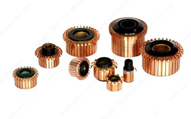
The diverse structures of plastic commutators are a direct response to the above requirements, with design parameters closely tied to motor power, voltage, speed, and dimensions. Currently, mainstream semi-plastic commutators typically consist of a plastic shell, commutator segments (copper bars), mica sheet insulation, and metal bushings. This combination ensures safety through insulating materials, guarantees reliable current conduction via metal components, and utilizes a plastic shell for lightweight construction and structural support—providing a foundation for optimizing motor performance in various applications. From industrial equipment to household appliances, commutators continuously enable efficient motor operation through precise structural design and stable current control.
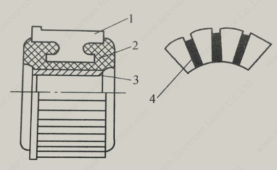
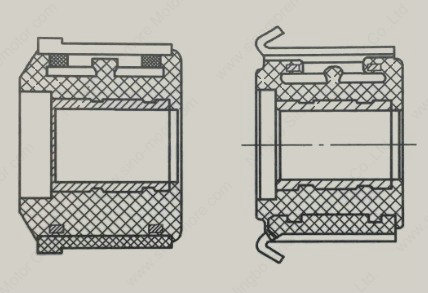
The figure shows a schematic diagram of the commutator structure. Here, 1 represents the commutator segment, responsible for switching current; 2 is the plastic shell, providing protection and support; 3 is the metal bushing, ensuring current transmission; and 4 is the mica sheet, serving as insulation to prevent short circuits. With this structural design, the commutator meets multiple performance requirements to ensure efficient and stable motor operation.
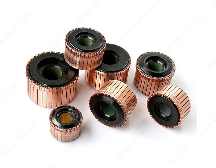
According to the difference in the connection structure between the commutator segment and the coil head, the commutator can be divided into slot commutators and hook commutators.
For slot commutators, grooves are milled on the raised parts of the commutator segments, and the coil heads are embedded in these grooves, followed by spot welding (hot pressure welding) technology. During the spot welding process, the paint film of the enameled wire is melted by high temperature, promoting good electrical connections between the wire heads and between the wire heads and the groove walls of the commutator.
 For hook commutators, when winding the rotor coil, the coil head is directly wound on the hook of the commutator segment. During spot welding, the hook is pressed down to achieve a good electrical connection between the wire head and the commutator. This type of commutator facilitates the automation of the connection process between coil ends and the commutator, but is mostly used in scenarios with fewer commutator segments and lower motor power. This is because high-power motors have relatively thick coil wire diameters, making winding difficult. Additionally, when the number of commutator segments is large, the hook width narrows, and adjacent wire ends are extremely prone to short-circuiting.
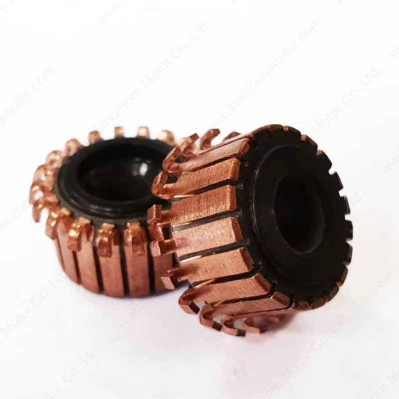
The shell of the commutator is generally made of glass fiber reinforced thermosetting plastic or asbestos plastic. Because the commutator generates heat during operation and needs to bear certain mechanical stress, the requirements for the heat resistance and mechanical strength of the plastic are strict. At the same time, its thermal expansion coefficient also needs to be as close as possible to that of the copper commutator. Phenolic resin bakelite powder is usually used to meet these requirements.The main function of the metal bushing is to prevent the plastic from bearing mechanical stress when the commutator is pressed onto the shaft. However, due to size limitations, small commutators often do not have metal bushings. Common metal bushings include brass bushings, spring bushings and other types.
Mica plates or mica powder are used for insulation between commutator segments. Due to the extremely strong wear resistance of mica, it is necessary to use a grooving process to make the mica plate between the segments lower than the surface of the commutator segments to avoid the wear-resistant mica plate protruding and affecting the contact between the brush and the commutator segment. If the mica plate protrudes, it will lead to a decline in commutation performance and even cause the motor to fail to work normally.
The materials of the commutator copper bars are mainly divided into two categories: one is oxygen-free copper or electrolytic copper, which is suitable for scenarios with low rotation speed, such as small household appliance motors and automotive starters; the other is silver-copper alloy, which is commonly used in equipment such as vacuum cleaners and power tools. Because the linear speed during commutation of such equipment is high, spark erosion is likely to cause the surface temperature of the commutator to rise rapidly. The silver element added in the silver-copper alloy can improve the high-temperature resistance of the material, make the surface of the commutator not easy to deform, and effectively suppress defects such as spark erosion and poor contact, so as to ensure stable operation under high-speed working conditions.